|
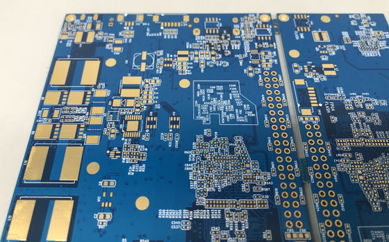
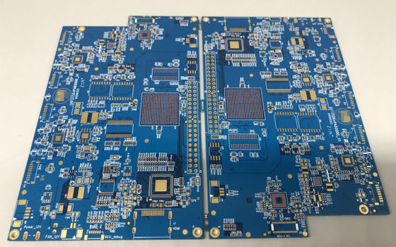
HDI PCB is the shortened form of High Density Interconnector PCB. It's a technology of printed circuit board production.
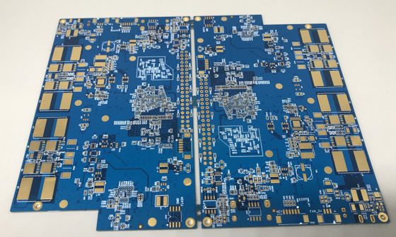
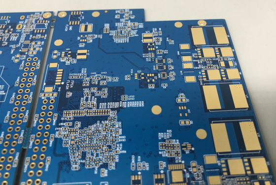
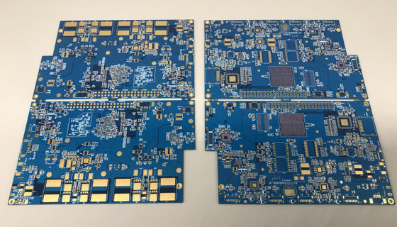
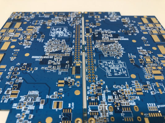
This is a circuit board that uses micro-blind buried hole technology, with very high line density and complexity, and can achieve high-speed signal transmission and reliability design. The main features of HDI circuit boards are multi-layer lines, thin plates, small apertures, dense wiring and fine lines, and are widely used in mobile phones, computers, network communications, automotive electronics and other fields.
The manufacture of HDI circuit boards is one of the fastest-growing areas in the printed circuit board industry. It is a compact product designed for small-capacity users. As electronic products develop towards high density and high precision, HDI circuit boards have put forward the same requirements accordingly. The production of HDI boards uses advanced fine line production technology, so that the line width and spacing reach the micron level. This high-precision line layout not only improves the performance of the circuit board, but also reduces energy consumption and electromagnetic interference. Therefore, HDI circuit boards are widely used in high-end electronic devices such as smartphones, tablets, and laptops.
In the manufacturing process of HDI circuit boards, the process of drilling and metallization in the holes is used to achieve the connection function between the lines of each layer. Compared with traditional multi-layer circuit boards, HDI circuit boards adopt the build-up method, use blind and buried vias to reduce the number of through holes, save the PCB wiring area, and thus greatly increase the density of components. Therefore, they have quickly replaced the original multi-layer boards in the use of smart phones. With the continuous advancement of electronic technology, electronic products continue to develop in the direction of light, thin, short and small, and high-density interconnect (HDI) technology has come into being.
Product Details:
Payment & Shipping Terms:
|
Layer Count: | 4Layers | Max Board Size: | 600 Mm X 1200 Mm |
---|---|---|---|
Base Material For PCB: | FR4 | Rang Of Finish Baords Thickness: | 0.21-7.0mm |
Minimum Line Width: | 3mil (0.075mm) | Minimum Hole Diameter: | 0.10 Mm |
Finishing Treatment: | HASL (Tin-Lead Free), ENIG(Immersion Gold), Immersion Silver , Gold Plating (Flash Gold), OSP, Etc. | Thickness Of Copper: | 0.5-14oz (18-490um) |
E-Testing: | 100% E-Testing (High Voltage Testing); Flying Probe Testing | ||
Highlight: | blind via pcb,lead free pcb |
10pcs,TQFP-64 TQFP-48 TO DIP FR4 PCB Printed Circuit adapter Test Board
1. Features
1. One Stop OEM Service, Made in Shenzhen of China
2. Manufactured by Gerber File and BOM List from Customer
3. FR4 Material, Meet 94V0 standard
4. SMT, DIP technology suport
5. Lead Free HASL, Environmental Protection
6. UL, CE, ROHS Compliant
7. Shipping By DHL,UPS, TNT, EMS or Customer requirement
2. PCB Technical capability
SMT | Position accuracy:20 um |
Components size:0.4×0.2mm(01005) —130×79mm,Flip-CHIP,QFP,BGA,POP | |
Max. component height::25mm | |
Max. PCB size:680×500mm | |
Min. PCB size:no limited | |
PCB thickness:0.3 to 6mm | |
PCB weight:3KG | |
Wave-Solder | Max. PCB width:450mm |
Min. PCB width: no limited | |
Component height:Top 120mm/Bot 15mm | |
Sweat-Solder | Metal type :part, whole, inlay, sidestep |
Metal material:Copper , Aluminum | |
Surface Finish:plating Au, plating sliver , plating Sn | |
Air bladder rate:less than20% | |
Press-fit | Press range:0-50KN |
Max. PCB size:800X600mm | |
Testing | ICT,Probe flying,burn-in,function test,temperature cycling |
2. PCB Pictures
Contact Person: Mrs. Helen Jiang
Tel: 86-18118756023
Fax: 86-755-85258059